




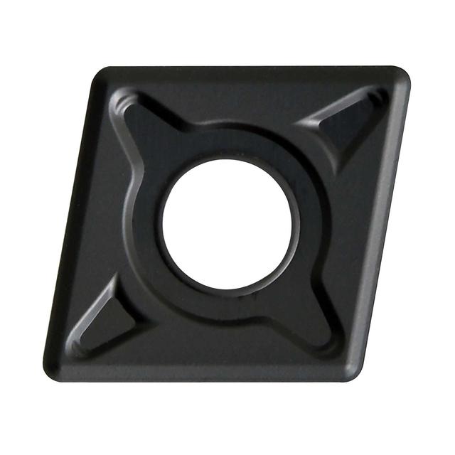
CNMG-EM carbide turning insert
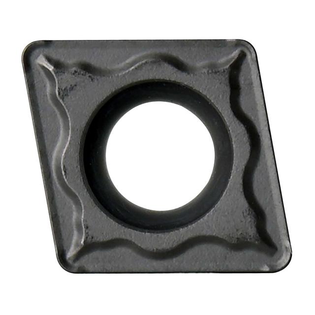
CCMT-EM carbide turning insert
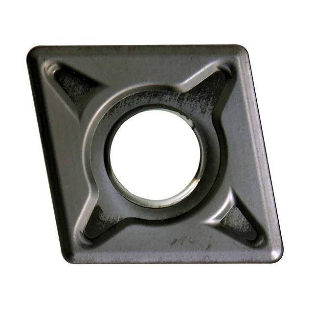
CNMG-EM carbide turning insert
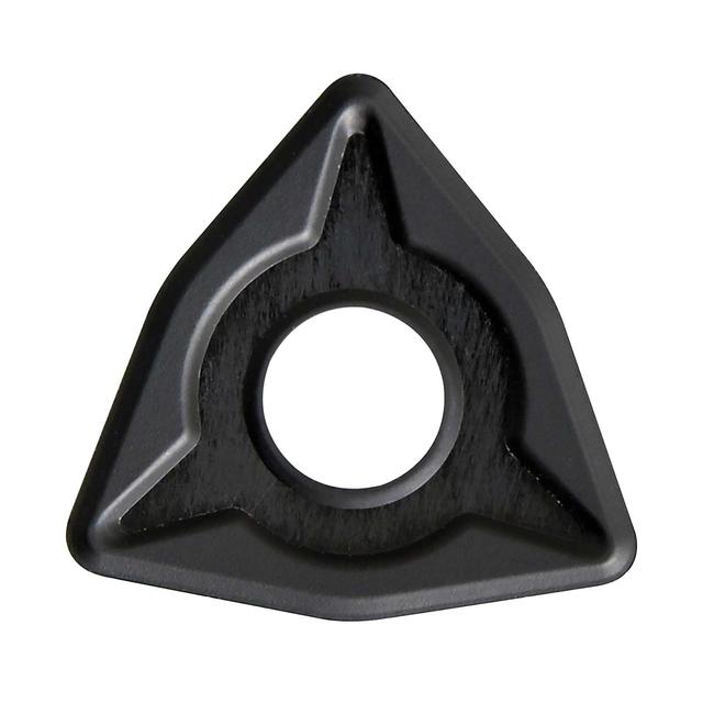
WNMG-EM carbide turning insert
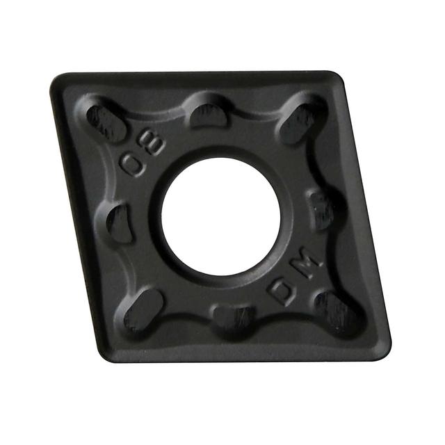
CNMG-DM carbide turning insert
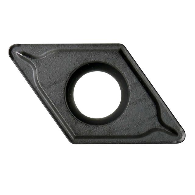
DCMT-EM carbide turning insert
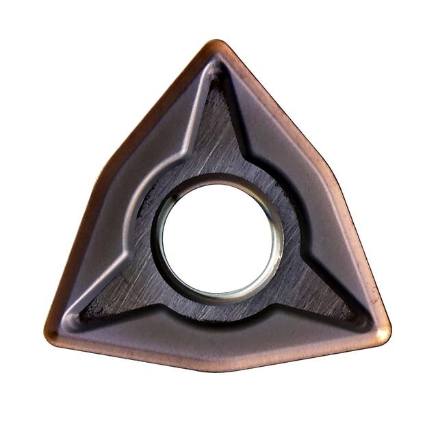
WNMG-EM carbide turning insert
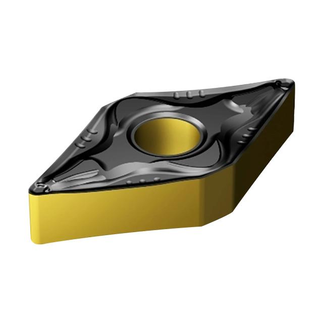
DNMG-EM carbide turning insert
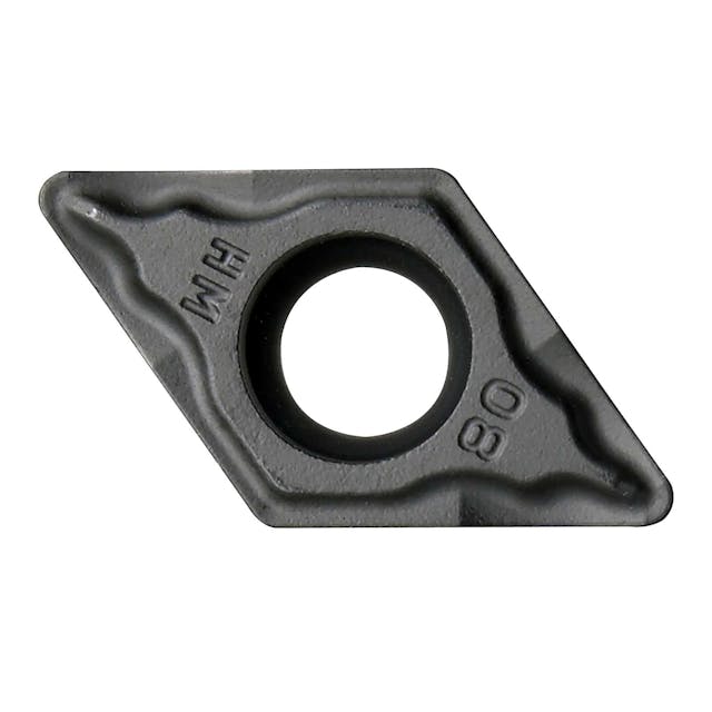
DCMT-HM carbide turning insert
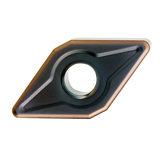
DNMG-EM carbide turning insert
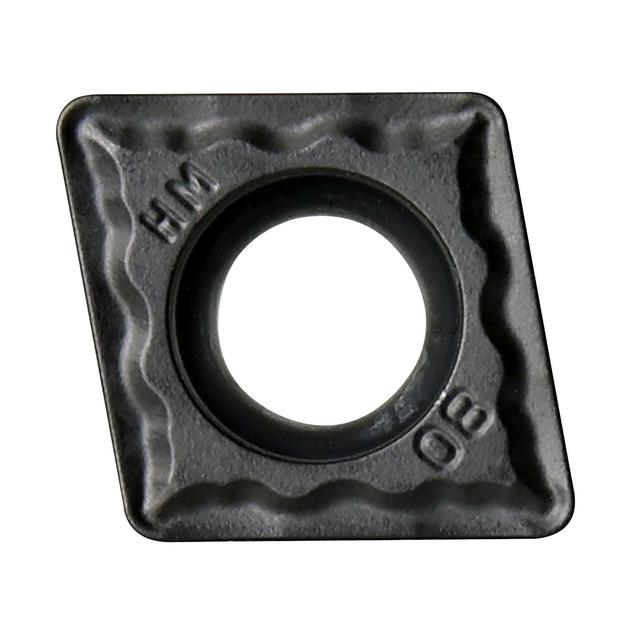
CCMT-HM carbide turning insert
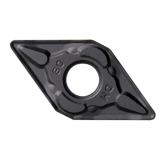
DNMG-DM carbide turning insert
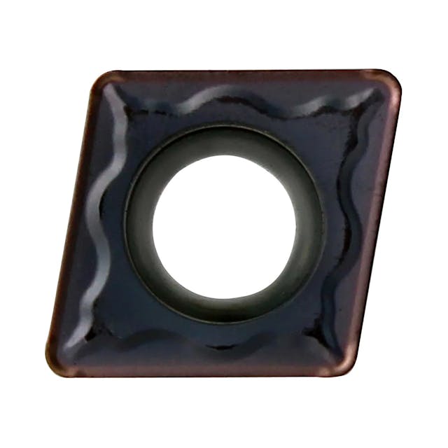
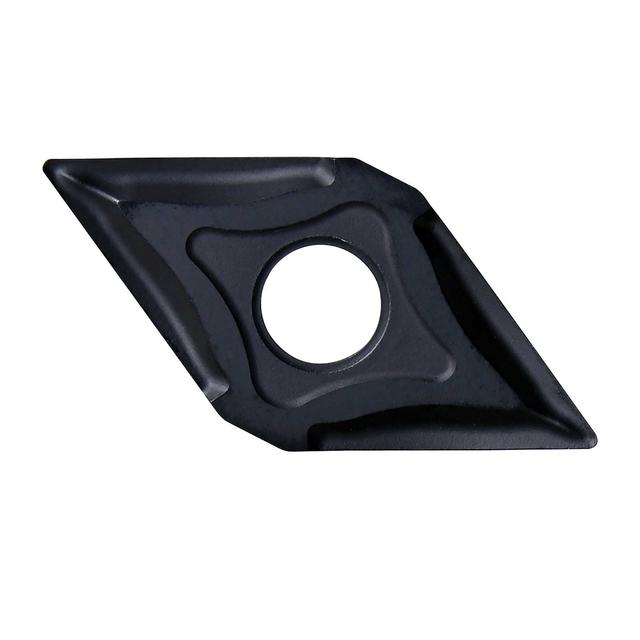
DNMG-EF carbide turning insert for finishing
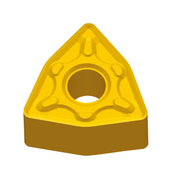
WNMG-DM carbide turning insert
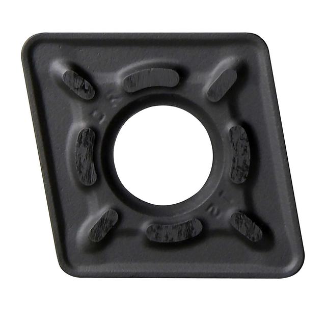
CNMG-DR carbide turning insert for roughing
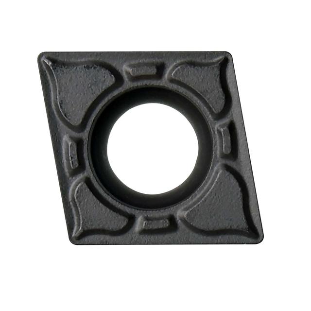
CCMT-EF carbide turning insert for finishing
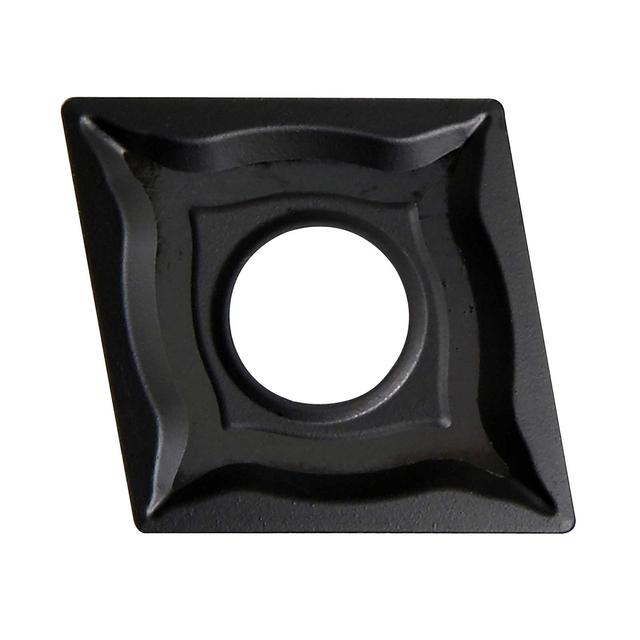
CNMG-EF carbide turning insert for finishing
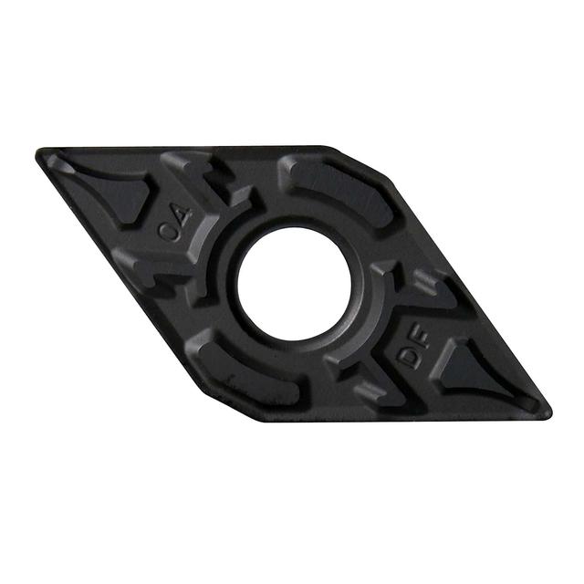
DNMG-DF carbide turning insert for finishing
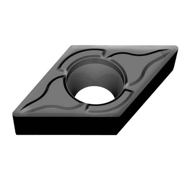
DCMT-EF carbide turning insert for finishing
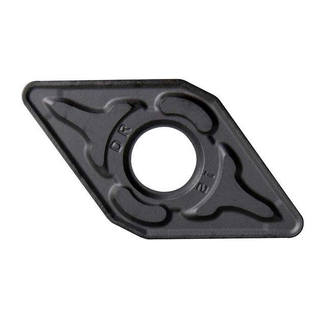
DNMG-DR carbide turning insert for roughing
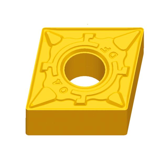
CNMG-DF carbide turning insert for finishing
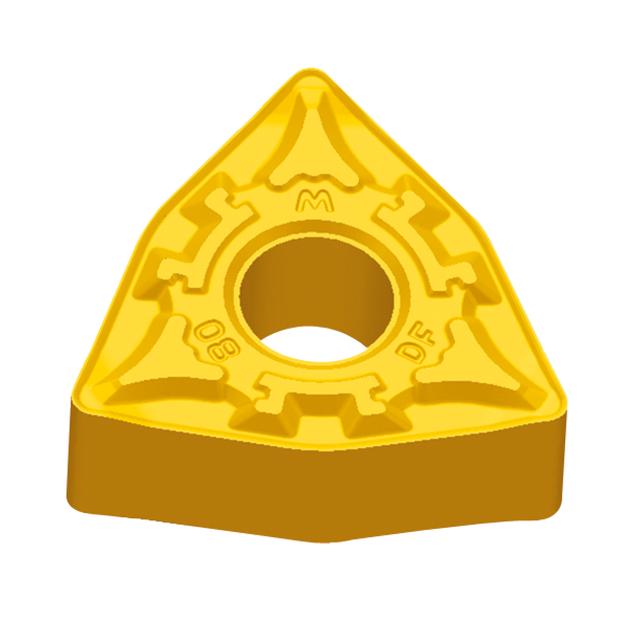
WNMG-DF carbide turning insert for finishing
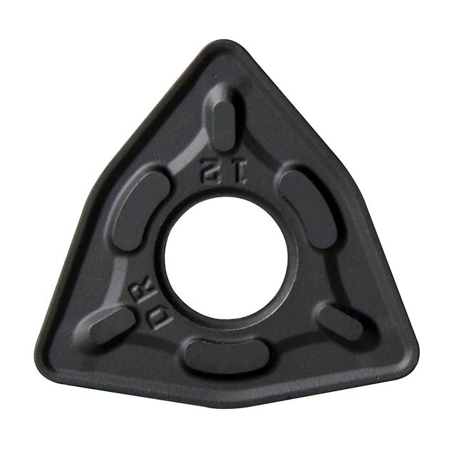
WNMG-DR carbide turning insert for roughing
Carbide turning inserts are replaceable cutting tips used in indexable turning tool holders on lathes and turning centres. These inserts are made from tungsten carbide, typically with a PVD or CVD coating which are held in a precision pocket in the tool holder and perform the actual metal cutting.
When a cutting edge becomes worn, the insert is rotated (indexed) to a fresh edge, or replaced entirely, without disturbing the tool holder setup. Carbide turning inserts offer significantly higher cutting speeds and longer tool life compared to HSS tooling.
ISO insert part numbers follow a standardised, 7-character code.
For example, CNMG 120408 KM:
C - Insert shape (C = 80° rhombic; D = 55° rhombic; T = triangular; V = 35° rhombic; S = square; W = 80° trigon; K = 55° parallelogram; R = round)
N - Clearance/relief angle (N = 0°; A = 3°; B = 5°; C = 7°; P = 11°; G = 30°)
M - Tolerance class (M = medium; G = precision ground; U = untolerance ground)
G - Insert form/chipbreaker style (G = with chipbreaker, central hole; no letter = flat top; other letters denote specific features)
12 - Insert size (inscribed circle in mm: 06, 09, 12, 16, 19…)
04 - Insert thickness in mm
08 - Corner/nose radius × 10 (08 = 0.8mm nose radius)
KM - Chipbreaker designation (e.g. KF = finishing, KM = medium, KR = roughing)
Understanding this system allows you to identify compatible inserts across brands and quickly find replacements.
Insert shape affects the number of usable edges, strength, and versatility:
CNMG / CCMT / CCGT (80° rhombic) - strong, versatile; suitable for general turning, facing, and profiling; 2 usable edges per insert
DNMG / DCMT / DCGT (55° rhombic) - more pointed; better for profiling, angled faces, and undercutting; 2 usable edges
SNMG (90° square) - 4 usable edges; strong and economical for roughing and medium machining
WNMG (80° trigon) - 3 strong, wide-angle edges; excellent for heavy roughing
VNMG / VCMT / VCGT (35° rhombic) - very sharp, pointed geometry for finishing, fine profiling, and difficult-to-reach features
VBMT (35° rhombic, positive) - similar to VNMG but with positive rake for lighter cutting forces
RCMT (round) - continuous cutting edge; ideal for profiling, copy turning, and heavy interrupted cuts
More usable edges = lower cost per edge.
Sharper angles = better access but weaker edge.
Negative rake inserts (e.g. CNMG, DNMG, WNMG) - have a 0° relief angle and they are used in negative-rake tool holders. The cutting edge is very strong and can withstand heavy cuts and interrupted cutting. The same insert can often be flipped and used on both sides, doubling the number of cutting edges. Best for roughing and general machining on steel and cast iron
Positive rake inserts (e.g. CCMT, DCMT, TCGT, VCGT) - have a ground clearance angle and are used in positive-rake holders. The sharper cutting geometry reduces cutting forces, minimises heat and produces better surface finishes. Ideal for finishing, lighter cuts, stainless steel, aluminium and softer materials.
The chipbreaker is the moulded or ground geometry on the insert face that controls chip formation and breaking.
The code typically indicates both the chipbreaker geometry and the intended operation:
F (Finishing) — shallow depth grooves, light feeds; produces fine surface finish; e.g. KF, DF, EF, LF, HF, PF
M (Medium) — balanced geometry for medium depth of cut and feed; versatile all-round use; e.g. KM, DM, EM, LM, HM, PM
R (Roughing) — robust geometry for deep cuts and high feeds; strong edge, handles interrupted cuts; e.g. KR, DR, PR, AR.
Matching the chipbreaker to your depth of cut and feed rate is as important as selecting the correct grade as using the wrong chipbreaker will result in poor chip control, built-up edge, or premature insert failure.
The grade refers to the carbide substrate composition and coating. It determines how well the insert resists wear, heat, and edge deformation for a given material:
KA9000 (Universal) - CVD-coated universal grade that works across steel, stainless, and cast iron making it a versatile first choice when you machine multiple materials
P2501 - PVD-coated steel grade which is optimised for carbon and alloy steels and shows excellent wear resistance at higher cutting speeds
P3501 - PVD-coated grade for steel and stainless which gives it more toughness than P2501, making it good for interrupted cuts
M2501 - for stainless steel & heat-resistant super alloys, bringing sharp edge geometry with high edge toughness
N1001 - uncoated or lightly coated grade for aluminium & non-ferrous; with an ultra-sharp edge which prevents built-up edge
4325 (Sandvik Coromant) - premium grade for steel, stainless & cast iron
YBC152 / YBC252 / YBM153 / YBM253 / YBG205 (ZCC-CT) - application-specific coated grades covering steel, stainless, cast iron and super alloys at various machining conditions
Use our grade filter alongside the application and operation filters to find the best option for your material and cutting conditions.
The nose radius is the small radius at the tip of the turning insert (e.g. 0.2mm, 0.4mm, 0.8mm, 1.2mm).
It has a direct impact on both surface finish and edge strength:
Smaller nose radius (0.2–0.4mm) - better for profiling, fine finishing and undercutting which produces lower radial forces but a weaker tip and is best suited to light finishing passes
Larger nose radius (0.8–1.2mm) - has a stronger insert tip and can withstand heavier feeds, so in turn it produces better surface finish at higher feeds - this turning insert option preferred for roughing and medium machining.
As a general rule, your depth of cut should be greater than the nose radius to avoid rubbing and poor chip formation.
Our carbide turning inserts range covers all standard engineering materials:
Steel (P-grade) - carbon steel, alloy steel, tool steel - this is the most common application
Stainless steel (M-grade) - austenitic, duplex, martensitic stainless - requires tough, sharp inserts
Cast iron (K-grade) - grey, nodular & hardened cast iron - wear-resistant grades preferred
Aluminium & non-ferrous (N-grade) - aluminium alloys, copper, brass - uncoated or PVD-coated sharp inserts
Heat-resistant super alloys (S-grade) - Inconel, titanium, Hastelloy, Waspaloy - specialist grades with high edge toughness essential
Use the Application filter on our listings to quickly identify inserts rated for your specific material.
These designations refer to the intended depth of cut and feed rate range:
Finishing - light depth of cut (typically 0.1–1.0mm) with low to medium feed rate - priority is surface finish and dimensional accuracy
Medium machining - moderate depth of cut (0.5–3.0mm) with medium feed rate - the most versatile everyday turning operation
Roughing - heavy depth of cut (2.0mm+) with a high feed rate - priority is material removal rate; surface finish is secondary
Using a finishing insert for roughing risks chipping or fracture and using a roughing insert for finishing typically produces poor surface quality. Always match the chipbreaker and grade to the operation!
It depends on the turning insert shape and whether it is single or double-sided:
Single-sided negative inserts (e.g. CNMG, DNMG) - 2 usable edges (one per corner on each side, but used on one side only in standard holders)
Double-sided negative inserts - can be flipped for up to 4–6 usable edges depending on shape
Square inserts (SNMG) - 4 (single-sided) or 8 (double-sided) usable edges
Round inserts (RCMT) - one continuous cutting edge, rotated incrementally as it wears
More usable edges per insert = lower cost per edge over the lifetime of the insert pack!