




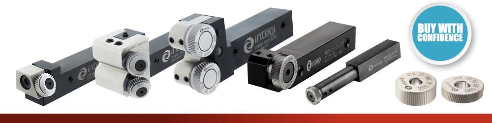
Features:
Features:
Features:
Features:
Features:
Features:
Machine Types:
Features:
Features:
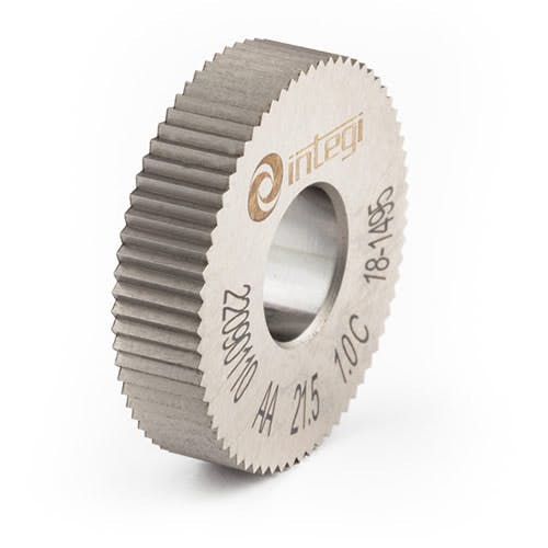
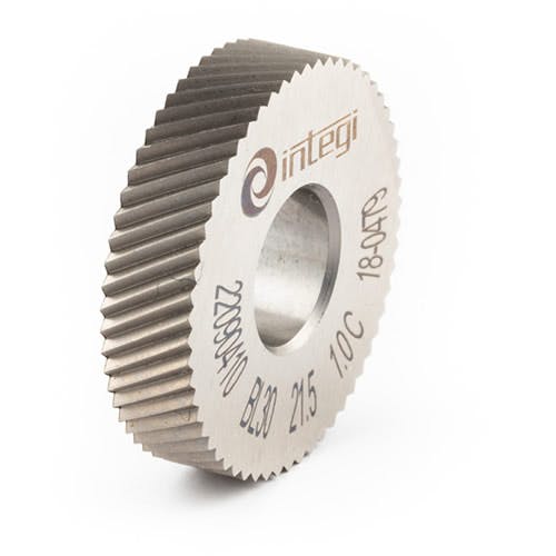
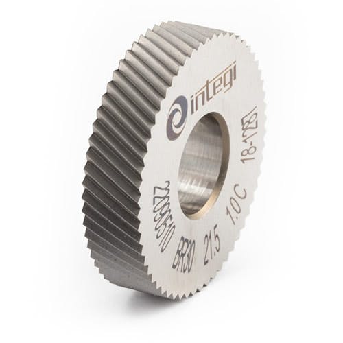
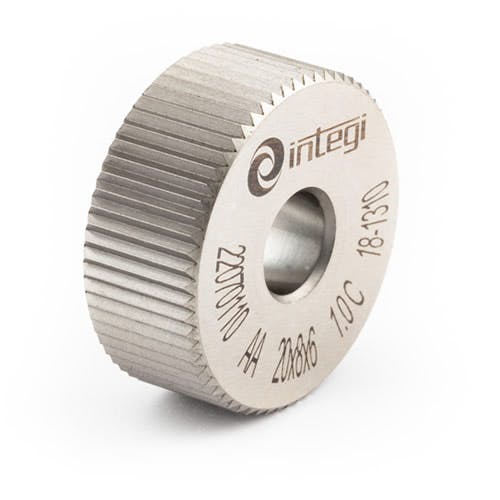
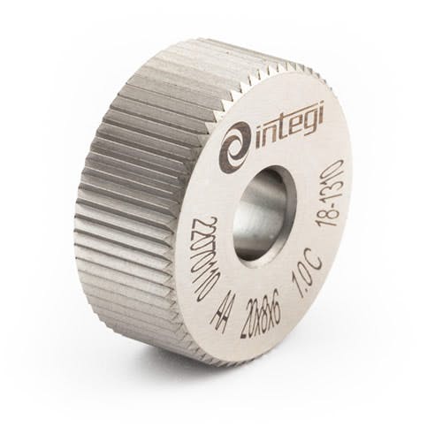
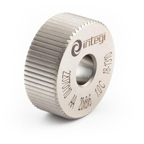
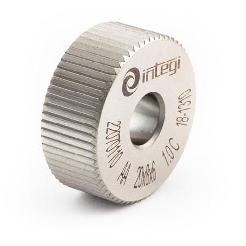
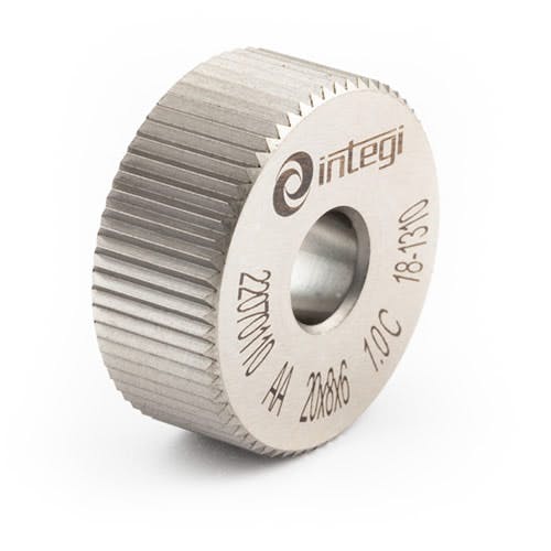
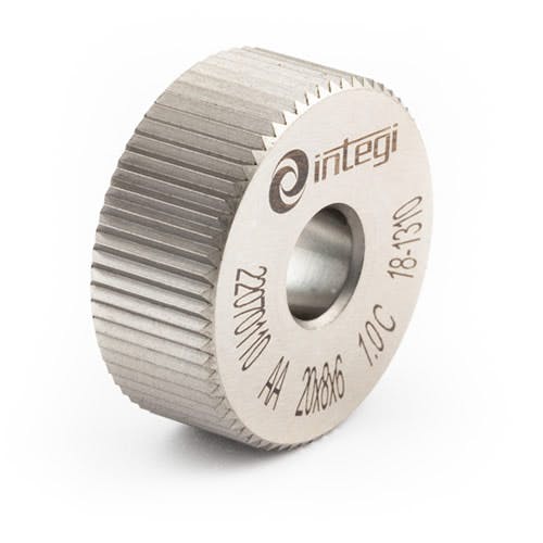
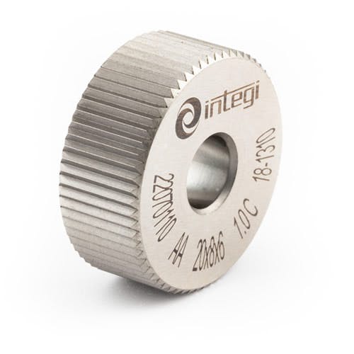
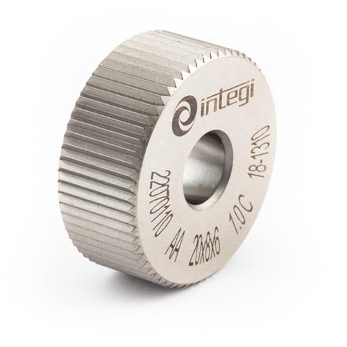
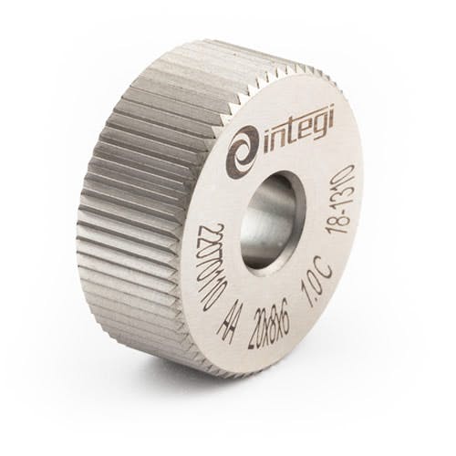
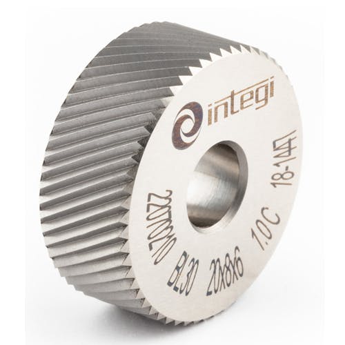
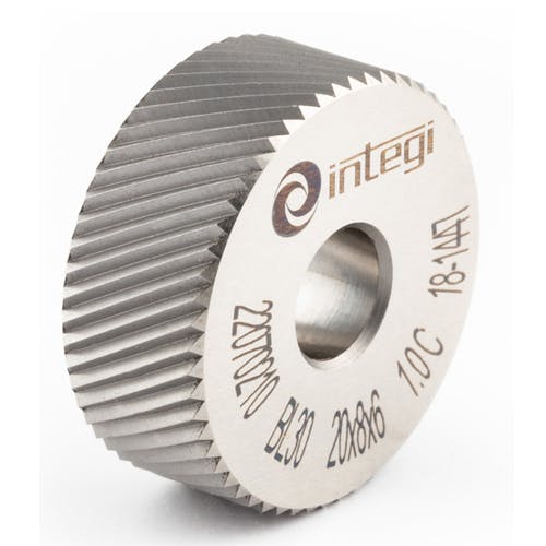
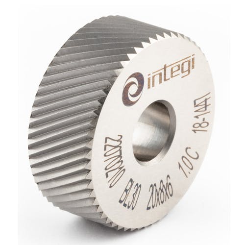
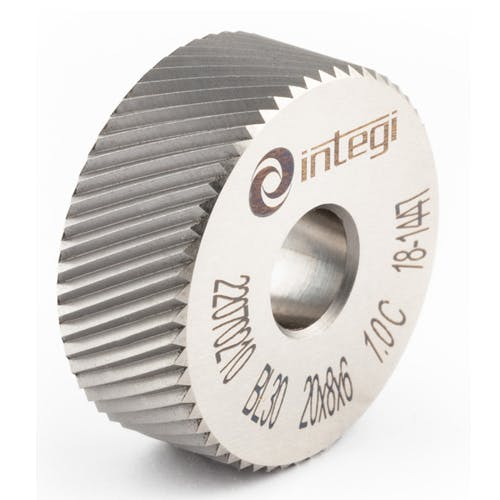
Knurling is a manufacturing process that produces a textured pattern on the surface of a workpiece (typically a cylindrical part turned on a lathe) by pressing a hardened wheel with a shaped profile against the rotating workpiece. The resulting pattern improves grip (for knobs, handles, thumb screws & caps), provides a decorative finish or increases the effective diameter of a part for press-fit assemblies.
Two fundamentally different knurling processes exist and the INTEGI tool range includes holders designed for each:
Form knurling (also called pressure knurling or deformation knurling) works by cold-forming the workpiece material. A hardened steel knurling wheel with the negative of the desired pattern is pressed into the workpiece surface under high pressure.
The wheel's teeth displace the workpiece material plastically pushing it both inward (creating valleys) and outward (creating ridges). No material is removed. Form knurling is designated as "RAA" (single wheel, against the workpiece) or "RGE" (dual wheel, opposing) type in the INTEGI system.
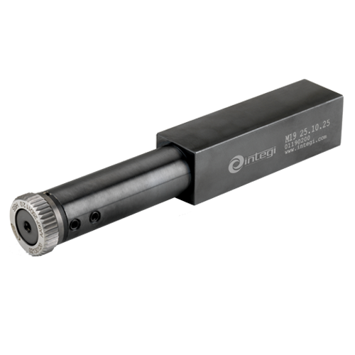
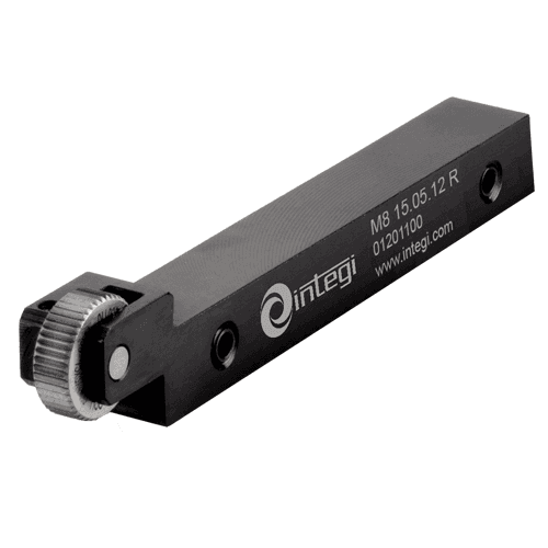
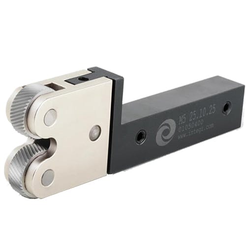
All of the M-series holders (M4, M5, M7, M8, M10, M11, M19) are form knurling holders.
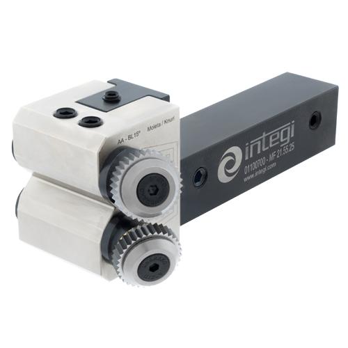
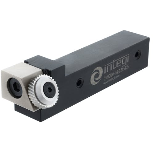
Cut knurling works by machining rather than deforming. A cutting knurling wheel (which has sharper, more defined cutting teeth) actually removes a small amount of material from the workpiece surface to create the pattern, similar to how a knurling cutting tool scrapes the surface. Cut knurling is designated for the MF21 series holder (described as a "Double Head Cut Knurling Holder") and the cutting knurling wheels are designated with the prefix "Cut-Knurls" on the product pages.
The practical differences: Form knurling produces a stronger, more work-hardened surface (because the material is compressed) and is the more common process for general-purpose grip patterns. It generates higher radial forces on the lathe and is better suited to rigid machines and larger diameter work. Cut knurling produces a cleaner, more defined pattern with lower radial forces, making it suitable for lower-rigidity setups, thin-walled or delicate workpieces and harder materials where form knurling might crack the surface. Cut knurling does produce swarf (chips) that must be cleared whereas form knurling produces none.
The INTEGI knurling wheel part numbers follow a systematic encoding that identifies the wheel dimensions, the tooth profile, the material, and the pitch.
The format is: KW [D][W][B] - [Pitch][Form][Material]
Where:
KW = Knurling Wheel
D = Wheel diameter in mm (10, 15, 20, 21.5 or 25)
W = Wheel width in mm (4, 5, 6, 8, 10 or 12)
B = Bore diameter in mm (4, 6 or 8)
Pitch = The tooth pitch in mm (encoded as 04 = 0.4mm, 05 = 0.5mm, 06 = 0.6mm, 07 = 0.7mm, 08 = 0.8mm, 10 = 1.0mm, 12 = 1.2mm, 15 = 1.5mm, 16 = 1.6mm, 18 = 1.8mm, 20 = 2.0mm)
Form = The tooth profile angle and direction (AA, BL30, BL45, GV30, GV45, GE45, BR30)
Material = HC = HSS Cobalt (8% cobalt high-speed steel)
Example: KW25108-06AAHC decodes as: KW (knurling wheel) / 25 (25mm diameter) / 10 (10mm width) / 8 (8mm bore) - 06 (0.6mm pitch) / AA (90° straight profile) HC (HSS Cobalt material).
The wheel dimensions (diameter × width × bore) must match the "Applicable Wheel" specification on the holder. For example the M4-INTEGI holder lists applicable wheels of 20x8x6, 20x10x6, 25x8x8, 25x10x8 and 25x12x8. You must select a wheel whose dimensions match one of these specifications.
The pitch is selected based on the desired knurl pattern spacing as finer pitches (0.4-0.6mm) produce a fine, dense pattern; coarser pitches (1.5-2.0mm) produce a bold, coarse pattern.
The form/profile designation (AA, BL30, etc.) determines the visual appearance of the knurl and must be selected in matching pairs for RGE (dual wheel) knurling to produce the correct diamond or cross pattern.
Seven profile designations are available, each producing a different visual pattern on the workpiece surface. The profile is determined by the angle of the teeth on the wheel relative to the wheel axis, and whether they angle left or right:
AA (90° Straight): The teeth run straight across the wheel face at 90° to the wheel axis (parallel to the workpiece axis when mounted). Produces straight parallel lines along the workpiece length. This is a straight knurl (the simplest pattern, producing a series of parallel ridges running along the workpiece axis). Used alone for straight-line grip patterns. When two AA wheels are used together in opposing configuration, they can produce a diamond pattern, though typically diamond patterns are produced using opposing angled wheels.
BL30 (30° Left Hand): Teeth angled at 30° to the wheel axis, leaning to the left. When used alone, produces a diagonal line pattern at 30° to the workpiece axis. When paired with a BR30 (right hand) wheel in an RGE dual-head holder, the two opposing 30° angles produce a diamond knurl pattern.
BR30 (30° Right Hand): Teeth angled at 30° to the wheel axis, leaning to the right. The mirror of BL30. Used in cut knurling (the KW21558-BR30HC is a Cut-Knurl). Paired with BL30 to produce a 30° diamond pattern.
BL45 (45° Left Hand): Teeth angled at 45°, leaning left. A steeper diagonal than BL30. Produces a 45° diamond pattern when paired with a right-hand counterpart.
GV30 (30° Cross Down): A cross pattern variant with 30° teeth. The "cross" designation indicates the teeth produce a crossed pattern. "Down" refers to the direction of the cross relative to the workpiece axis.
GV45 (45° Cross Down): A 45° cross pattern variant, downward direction.
GE45 (45° Cross Up): A 45° cross pattern variant, upward direction. Paired with GV45 to produce a diamond pattern with 45° angles.
The selection of profile determines the visual pattern: straight (AA alone), diagonal (BL or BR alone), or diamond/cross (paired opposing-angle wheels). Diamond knurling (the most common grip pattern) requires two wheels of opposite hand (e.g. BL30 + BR30, or GV45 + GE45) mounted in a dual-head (RGE type) holder.
RAA and RGE are INTEGI's designations for the two configurations of form knurling, referring to the number of knurling wheels and how they engage the workpiece:
RAA type knurling (single-wheel, radial): A single knurling wheel is pressed radially against the workpiece from one side. The wheel forms the pattern by displacing material inward and outward as the workpiece rotates. RAA is the simpler configuration because it uses a single head holder, requires less setup and produces lower total radial force on the workpiece. However, because the force is applied from one side only, the workpiece is subjected to a one-sided radial load that can deflect thin or long workpieces and the pattern formation relies on the single wheel pushing material both ways.
RAA is recommended for the single-head holders: M8, M4, M10 and M19 (internal). These holders carry one wheel.
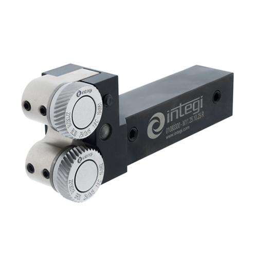
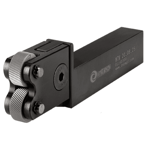
RGE type knurling (dual-wheel, opposing): Two knurling wheels are mounted on opposite sides of the workpiece, pressing inward from both sides simultaneously. The opposing forces partially cancel each other, significantly reducing the net radial load on the workpiece and minimising deflection. RGE is the preferred configuration for longer workpieces, thinner-walled parts and when a diamond pattern is required (two opposing-angle wheels produce the diamond). The two wheels must have matching pitches and complementary profiles (e.g. a left-hand and a right-hand wheel) to produce the correct pattern.
RGE is recommended for the double-head holders: M7, M5 and M11. These holders carry two wheels in opposing configuration.
The choice between RAA and RGE depends on the workpiece geometry and the pattern required. For a straight (AA) pattern on a short, rigid workpiece, RAA with a single-head holder is sufficient. For a diamond pattern on any workpiece or for knurling longer/thinner parts that would deflect under single-sided force, RGE with a double-head holder is the correct choice.
"Knurling up to a shoulder" refers to the ability of the knurling tool to form a knurl pattern right up to a shoulder, step or face on the workpiece where the knurled diameter meets a larger-diameter shoulder or a perpendicular face that the knurl pattern cannot cross.
On a standard knurling holder, the wheel is mounted in the centre of the holder head, meaning there is a finite distance between the wheel's edge and the side of the holder body. If the workpiece has a shoulder close to the knurled section, the holder body will contact the shoulder before the wheel reaches the end of the knurl, leaving an un-knurled portion at the shoulder.
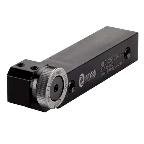
The M10-INTEGI and M11-INTEGI holders are specifically designed to solve this problem. Their head geometry positions the knurling wheel at the extreme end of the holder with the holder body behind the wheel rather than beside it. This allows the wheel to track right up to the shoulder face, ensuring the knurl pattern extends fully to the transition.
The M10 is a single-head (RAA) shoulder knurling holder and the M11 is a double-insert (RGE) shoulder knurling holder with pivoting head for self-centering - both accept 25x10x15/11 wheels and cover 8–200mm workpiece diameter.
Both shoulder holders use HSS bushings rather than carbide pins and both are supplied with an HSS hardened washer to prevent tool wearing at the wheel interface. The M10 is reversible (can fit right-hand or left-hand) while the M11 features the pivoting head for self-centering of the two knurls.
Successful knurling requires attention to setup, speed, feed, lubrication and technique. The following guidance applies to form knurling on a lathe using INTEGI holders:
Rigidity: Knurling generates very high radial forces, significantly higher than turning. The workpiece must be rigidly supported: use the tailstock centre for long workpieces, minimise workpiece overhang from the chuck and ensure the tool holder is clamped tightly with minimum overhang from the toolpost. A loose or flexible setup will produce a double-pattern, chatter or an incomplete knurl. If the workpiece deflects under knurling force, switch from a single-head (RAA) holder to a dual-head (RGE) holder to balance the forces.
Spindle speed: Knurling is performed at low spindle speeds (typically 50–150 RPM for medium-diameter workpieces (20-50mm)). The surface speed should be approximately 20-50 m/min, much slower than turning. Too high a speed causes the wheel to skid rather than roll, producing a smeared or double pattern and generating excessive heat.
Feed rate: The feed rate should be coarse enough that the wheel tracks in the grooves it has already formed. A typical feed is 0.3-0.8mm per revolution. Too fine a feed causes the wheel to re-engage the same groove repeatedly, producing a double pattern; too coarse a feed leaves an incomplete pattern. On the first pass, feed the tool into the workpiece radially until the full pattern depth is reached (the wheel should displace material to form the ridges), then feed axially along the workpiece to the end of the knurled section.
Pattern tracking: The most common knurling problem is a "double" or "overlaid" pattern, where the wheel does not track in the same grooves on successive revolutions. This is caused by the workpiece circumference not being an even multiple of the pitch. To avoid this, pre-turn the workpiece diameter so that (π x diameter) ÷ pitch = a whole number. For example, for a 0.8mm pitch wheel, a workpiece diameter of 12.7mm gives a circumference of 39.9mm ÷ 0.8 = approximately 49.9 teeth (close to a whole number). Fine-tuning the diameter by 0.1–0.3mm often resolves double-pattern issues.
Lubrication: Apply cutting fluid or lubricant liberally to the knurling zone. Form knurling generates high pressure and friction; lubricant reduces heat, prevents material pick-up on the wheel teeth and flushes any debris (in cut knurling). Use the same cutting fluid used for turning the workpiece material.
Engagement: Feed the wheel into the workpiece positively and decisively (a hesitant or too-light initial engagement causes the wheel to rub rather than form, work-hardening the surface and making subsequent pattern formation difficult). Once the full pattern depth is achieved, maintain consistent feed along the workpiece without disengaging. If a second pass is needed, re-engage at the starting point and feed in the same direction.
Clearance angle: The INTEGI holders feature adjustment of tool clearance angle by threaded studs integrated in the shank. Set the clearance angle so the wheel contacts the workpiece squarely (the wheel axis should be parallel to the workpiece axis). Incorrect clearance angle causes the wheel to rub on one side, producing an uneven pattern and accelerated wheel wear on one side.