




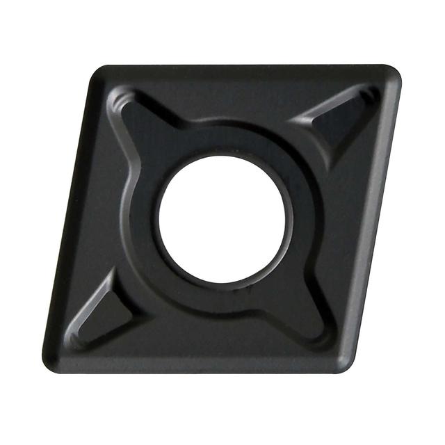
CNMG-EM carbide turning insert
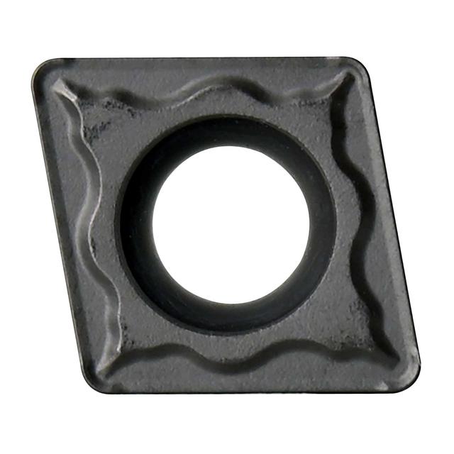
CCMT-EM carbide turning insert
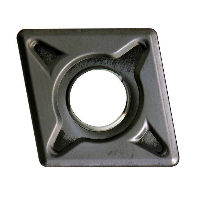
CNMG-EM carbide turning insert
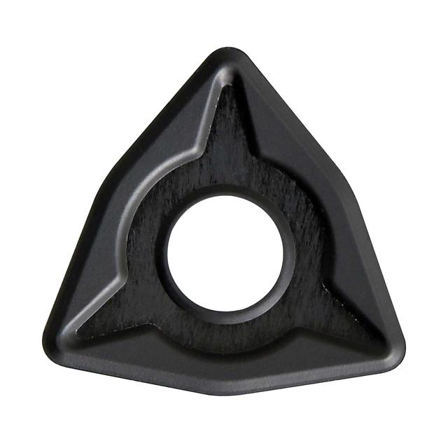
WNMG-EM carbide turning insert
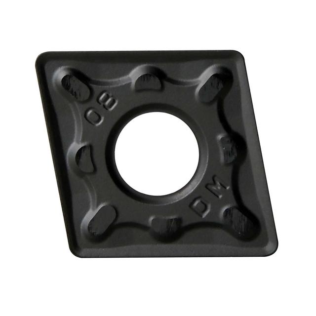
CNMG-DM carbide turning insert
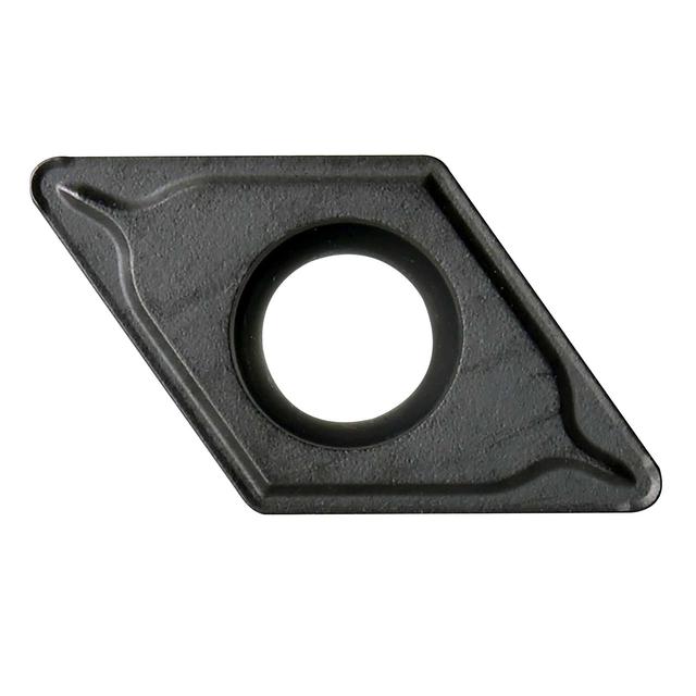
DCMT-EM carbide turning insert
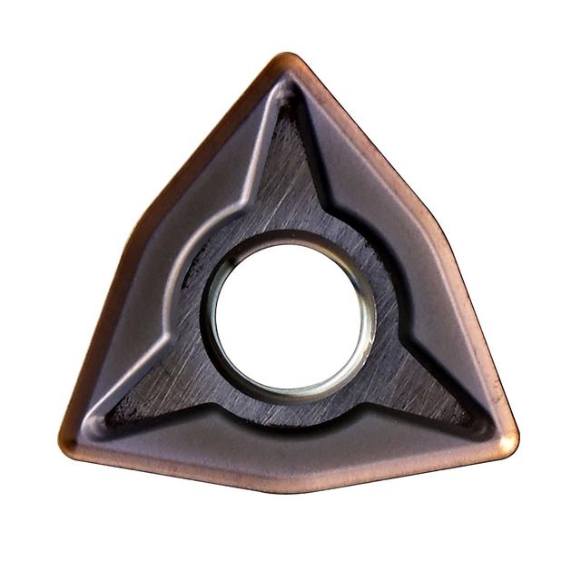
WNMG-EM carbide turning insert
.jpg&w=640&q=75)
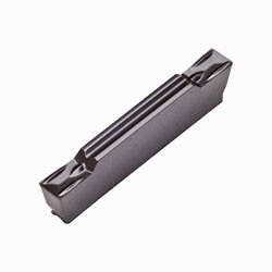
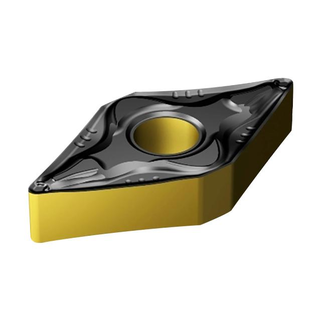
DNMG-EM carbide turning insert
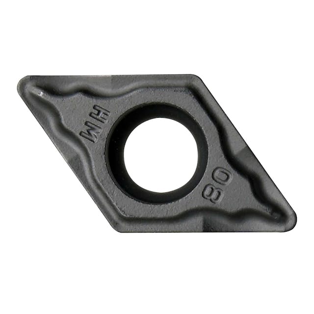
DCMT-HM carbide turning insert
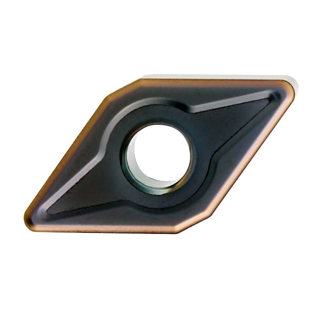
DNMG-EM carbide turning insert
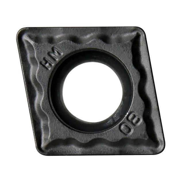
CCMT-HM carbide turning insert
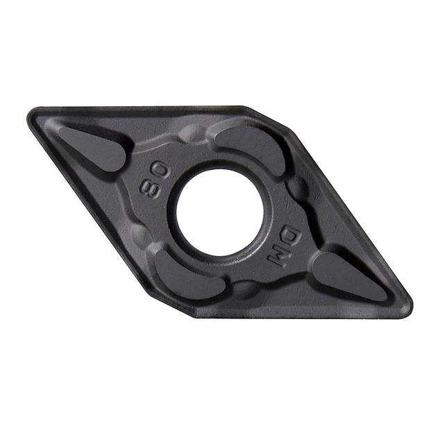
DNMG-DM carbide turning insert
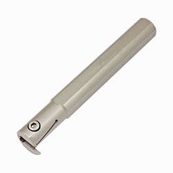
.jpg&w=640&q=75)

.jpg&w=640&q=75)
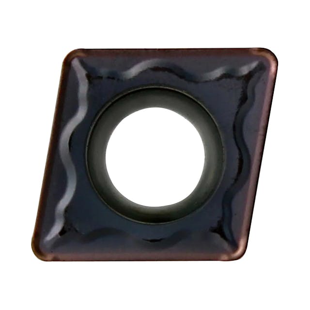
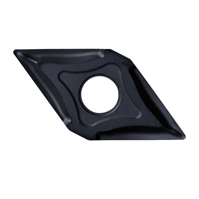
DNMG-EF carbide turning insert for finishing
.jpg&w=640&q=75)
Our lathe tools range covers three principal subcategories for turning operations on CNC and manual lathes:
Carbide Turning Inserts: indexable insert grades, geometries and chipbreakers for all turning operations with multiple brands and application-specific grades stocked covering steel, stainless steel, cast iron, aluminium & heat-resistant super alloys
ISO Toolholders: external turning tool holders in ISO standard styles for all common approach angles and insert shapes with both right and left-hand orientations
ISO Boring Bars: internal turning (boring) toolholders for machining bores and internal features which include dedicated Anti-Vibration Boring Systems for deep bore work
The clearance angle on the insert face is indicated by the second letter of the ISO code & determines whether the insert has positive or negative geometry:
Negative geometry (N — 0° clearance)
The turning insert has a flat bottom face and the clearance angle is generated by the toolholder's seat angle
Both faces of a double-sided insert can be used doubling the number of cutting edges per insert
Stronger & more robust cutting edge which is better for interrupted cuts, hard/tough materials, and heavy depths of cut
Slightly higher cutting forces than positive geometry
Positive geometry (clearance angle ground into the insert)
The insert itself carries a positive clearance angle; the cutting edge is sharper and enters the cut more cleanly
Lower cutting forces which are better for softer materials, thin-walled workpieces, low-power machines & finishing operations
Single-sided only (the clearance angle ground into the top face means the back face is not usable)
General rules of thumb:
Manual lathes and lower-power machines use positive geometry (lower cutting forces)
CNC lathes with good rigidity and adequate spindle power use negative geometry giving more edges per insert and better tool life
When finishing on any machine you should consider positive geometry for the reduced cutting forces and sharper edge.
The chipbreaker is the pattern of grooves, lands and angles pressed or ground into the insert face.
It breaks the chip into manageable lengths and controls its direction. Chipbreaker choice is as important as grade selection because even the correct grade will underperform with the wrong chipbreaker.
Chipbreakers in our range are classified by their primary operation:
Finishing chipbreakers (KF, DF, EF, HF, LF, AF, PF)
Designed for light depths of cut (typically 0.1–1.5mm ap) and high surface speed
Sharp edge entry with low cutting forces & good surface finish
Small chip groove dimensions so is optimised for thin chips at low feed rates
Not suitable for roughing depths as can overload at heavy cuts
Medium machining chipbreakers (KM, AM, LM, EM, DM, HM, PM)
The most versatile and widely used chipbreaker category
Covers the broadest range of depths of cut (typically 0.5–4.0mm ap) and feed rates
Good chip control across variable conditions - the recommended starting point if uncertain
EM chipbreaker (ZCC-CT) is widely regarded as the best first-choice chipbreaker for stainless steel; the CNMG120408-EM YBM253 is one of the most popular inserts in the range
Roughing chipbreakers (KR, AR, PR, DR)
For heavy depths of cut (typically 2.0–8.0mm+ ap) and high feed rates
Strong, wide chip groove; designed to handle the large, heavy chips of roughing
Higher edge strength than finishing geometry - designed for interrupted cuts
Coarser surface finish
Special chipbreakers:
AL = aluminium and non-ferrous; polished, wide-open groove for long, stringy aluminium chips -prevents built-up edge
Based on our range and our in-house engineers' recommendation the starting point for stainless steel turning is:
CNMG120408-EM YBM253 (ZCC-CT)
CNMG: 80° rhombic insert with a general-purpose shape - good for longitudinal turning
12: 12mm IC - standard size for medium-to-large toolholders (16–25mm shank)
04: 4mm thickness - standard
08: 0.8mm nose radius - the medium-machining general-purpose radius
EM: medium machining chipbreaker - designed for stainless steel and difficult materials
YBM253: PVD-coated grade optimised for stainless steel and difficult-to-machine materials at low-to-medium cutting speeds
For CNC high-speed turning of stainless steel consider Kato grade M2501 (PVD, specifically developed for stainless and HRSA) or P3501 (CVD, for interrupted stainless turning).
Key parameters for stainless turning:
Use sharp inserts (positive geometry preferred)
Avoid dwelling - programme the tool to retract rather than stop at the workpiece
Use adequate coolant
Ensure rigid setup - stainless vibration amplifies rapidly
Available corner radii: 0.2mm, 0.4mm, 0.8mm, 1.2mm, 1.6mm and 2.4mm (exact availability varies by insert type and brand).
The most stocked radii are 0.4mm and 0.8mm and together they cover the majority of general-purpose finishing and medium machining requirements.
If in doubt start with 0.8mm as it is the most widely stocked and the most versatile radius for medium machining across all common materials.