Filter by:
VDI Static Tool Holders for Use in CNC Turning Centres
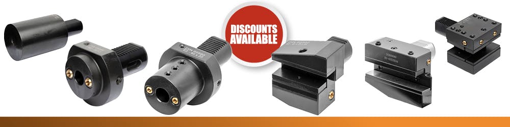
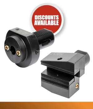
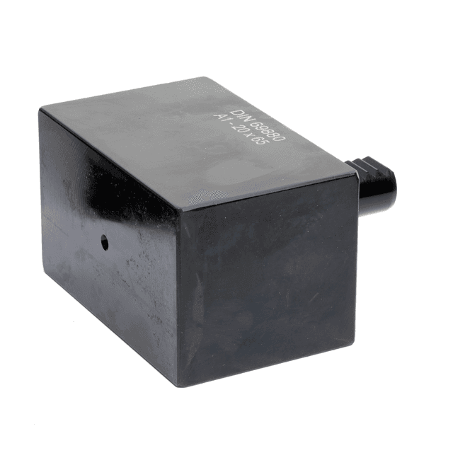
VDI A1 Pre Machined Rectangular Blank
Series: VDI-A1
VDI A1 pre machined rectangular tool blank. Manufactured to DIN69880 standard (ISO 10889).
Starting From:
£89.33 excl. VAT
£107.20 incl. VAT
£89.33 excl. VAT
£107.20 incl. VAT
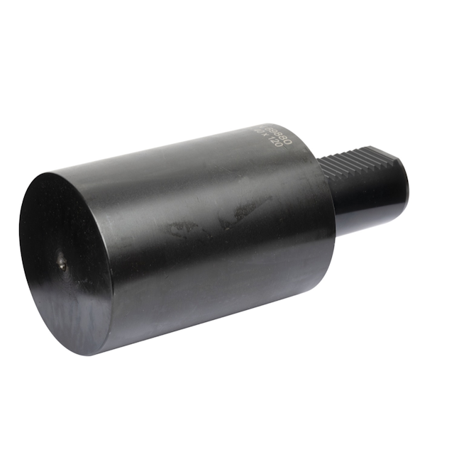
VDI A2 Pre Machined Circular Blank
Series: VDI-A2
VDI A2 pre machined circular blank tool. Manufactured to DIN69880 standard (ISO 10889).
Starting From:
£76.00 excl. VAT
£91.20 incl. VAT
£76.00 excl. VAT
£91.20 incl. VAT
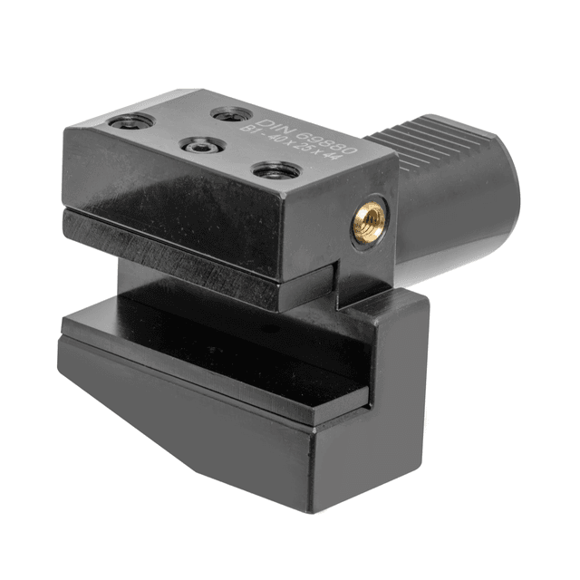
VDI B1 Radial Holders, Right Hand Short
Series: VDI-B1
VDI B1 radial holder for right handed short length turning tools. Tool holder for square shanked tools. Manufactured to DIN69880 standard (ISO 10889).
Starting From:
£76.00 excl. VAT
£91.20 incl. VAT
£76.00 excl. VAT
£91.20 incl. VAT
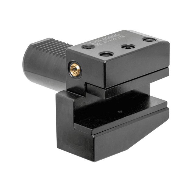
VDI B2 Radial Holders, Left Hand, Short
Series: VDI-B2
VDI B2 radial holder for left handed short length turning tools. Tool holder for square shanked tools. Manufactured to DIN69880 standard (ISO 10889).
Starting From:
£66.82 excl. VAT
£80.18 incl. VAT
£66.82 excl. VAT
£80.18 incl. VAT
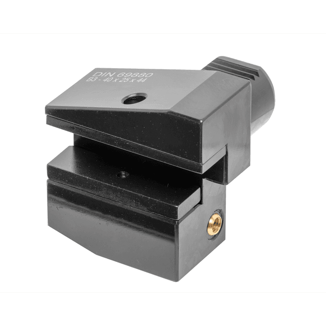
VDI B3 Radial Holders, Overhead Right Hand Short
Series: VDI-B3
VDI B3 radial holder for overhead right handed short length turning tools. Tool holder for square shanked tools. Manufactured to DIN69880 standard (ISO 10889).
Starting From:
£63.47 excl. VAT
£76.16 incl. VAT
£63.47 excl. VAT
£76.16 incl. VAT
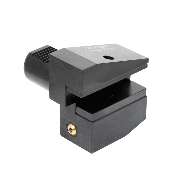
VDI B4 Radial Holders, Overhead Left Hand Short
Series: VDI-B4
VDI B4 radial holder for overhead left handed short length turning tools. Tool holder for square shanked tools. Manufactured to DIN69880 standard (ISO 10889).
In stock
Starting From:
£76.00 excl. VAT
£91.20 incl. VAT
£76.00 excl. VAT
£91.20 incl. VAT
Offer Price From:
£46.84excl. VAT
£56.21incl. VAT
£46.84excl. VAT
£56.21incl. VAT
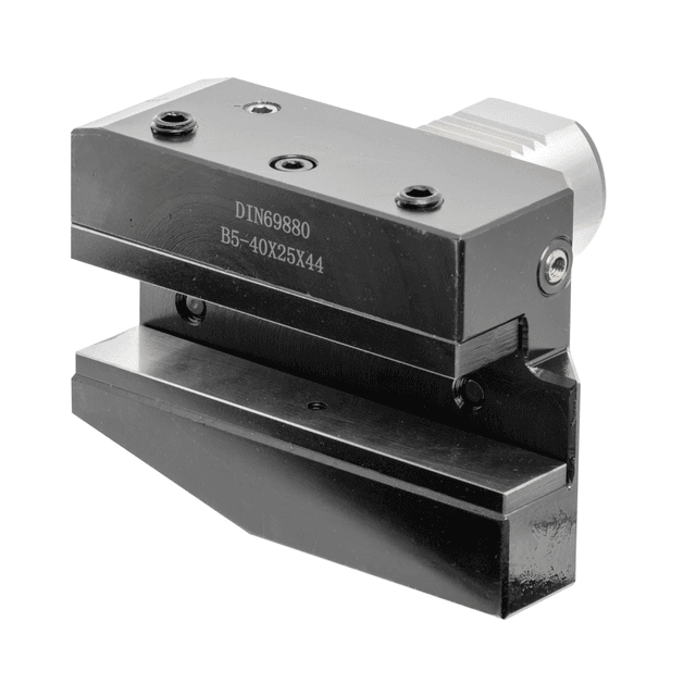
VDI B5 Radial Holders, Right hand Long
Series: VDI-B5
VDI B5 radial holder for right handed long length turning tools. Tool holder for square shanked tools. Manufactured to DIN69880 standard (ISO 10889).
Starting From:
£149.33 excl. VAT
£179.20 incl. VAT
£149.33 excl. VAT
£179.20 incl. VAT

VDI B6 Radial Holders, Left Hand Long
Series: VDI-B6
VDI B6 radial holder for left handed long length turning tools. Tool holder for square shanked tools. Manufactured to DIN69880 standard (ISO 10889).
Starting From:
£149.33 excl. VAT
£179.20 incl. VAT
£149.33 excl. VAT
£179.20 incl. VAT
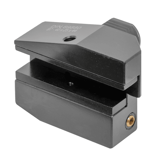
VDI B7 Radial Holders, Overhead Right Hand Long
Series: VDI-B7
VDI B7 radial holder for overhead right handed long length turning tools. Tool holder for square shanked tools. Manufactured to DIN69880 standard (ISO 10889).
Starting From:
£136.98 excl. VAT
£164.38 incl. VAT
£136.98 excl. VAT
£164.38 incl. VAT
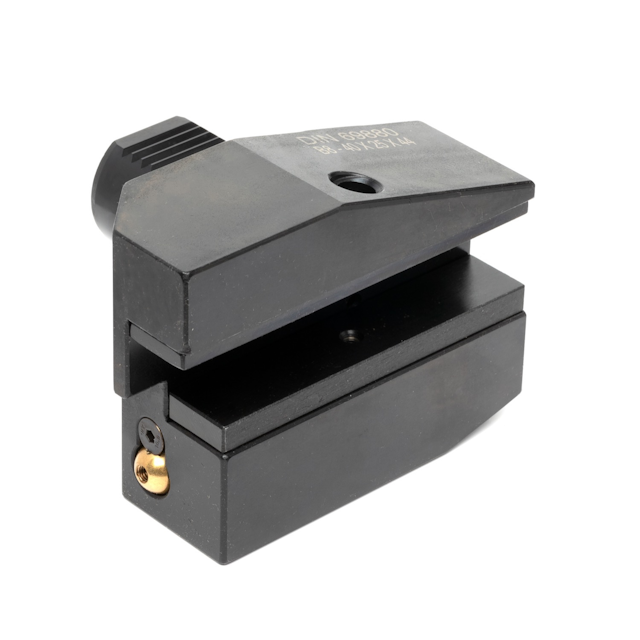
VDI B8 Radial Holders, Overhead Left Hand Long
Series: VDI-B8
VDI B8 radial holder for overhead left handed long length turning tools. Tool holder for square shanked tools. Manufactured to DIN69880 standard (ISO 10889).
Starting From:
£149.33 excl. VAT
£179.20 incl. VAT
£149.33 excl. VAT
£179.20 incl. VAT
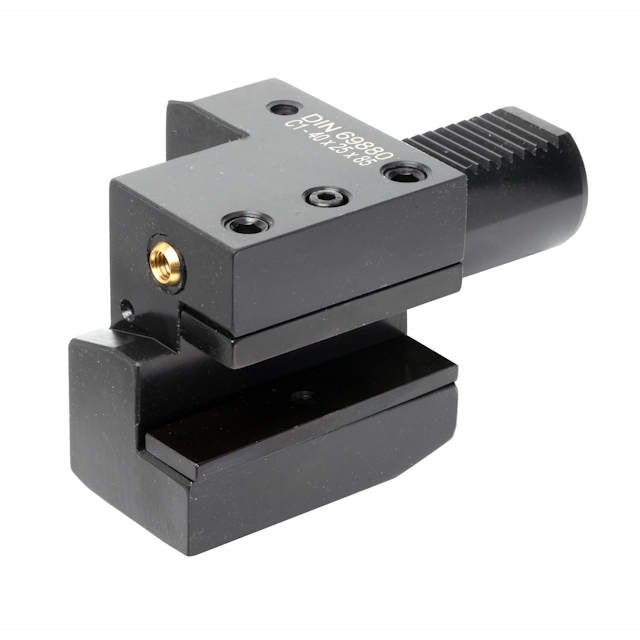
VDI C1 Axial Holders, Right Hand
Series: VDI-C1
VDI C1 axial holder for right handed turning tools. Tool holder for square shanked tools. Manufactured to DIN69880 standard (ISO 10889).
Starting From:
£86.67 excl. VAT
£104.00 incl. VAT
£86.67 excl. VAT
£104.00 incl. VAT
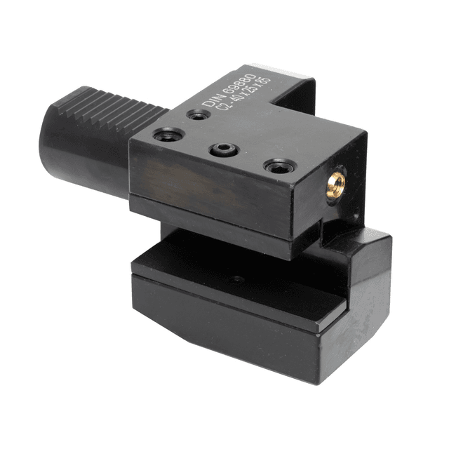
VDI C2 Axial Holders, Left Hand
Series: VDI-C2
VDI C2 axial holder for left handed turning tools. Tool holder for square shanked tools. Manufactured to DIN69880 standard (ISO 10889).
Starting From:
£86.67 excl. VAT
£104.00 incl. VAT
£86.67 excl. VAT
£104.00 incl. VAT
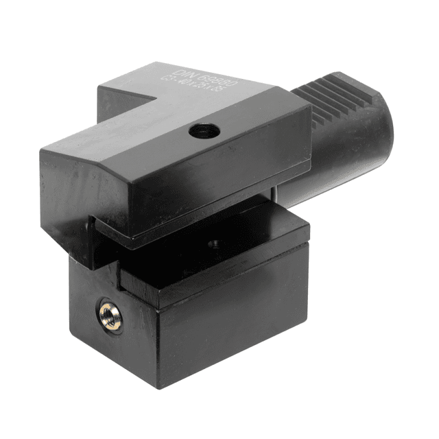
VDI C3 Axial Holders, Overhead Right Hand
Series: VDI-C3
VDI C3 axial holder for overhead right handed turning tools. Tool holder for square shanked tools. Manufactured to DIN69880 standard (ISO 10889).
Starting From:
£74.61 excl. VAT
£89.53 incl. VAT
£74.61 excl. VAT
£89.53 incl. VAT
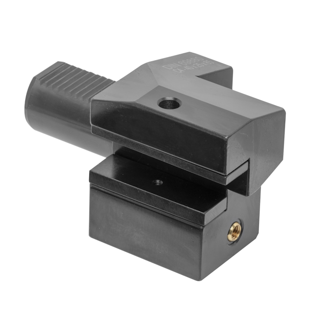
VDI C4 Axial Holders, Overhead Left Hand
Series: VDI-C4
VDI C4 axial holder for overhead left handed turning tools. Tool holder for square shanked tools. Manufactured to DIN69880 standard (ISO 10889).
Starting From:
£86.67 excl. VAT
£104.00 incl. VAT
£86.67 excl. VAT
£104.00 incl. VAT
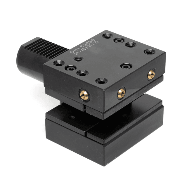
VDI D1 Square Seat Holder
Series: VDI-D1
VDI D1 square seat holder. Multiple square seat holder. Manufactured to DIN69880 standard (ISO 10889).
Starting From:
£213.33 excl. VAT
£256.00 incl. VAT
£213.33 excl. VAT
£256.00 incl. VAT
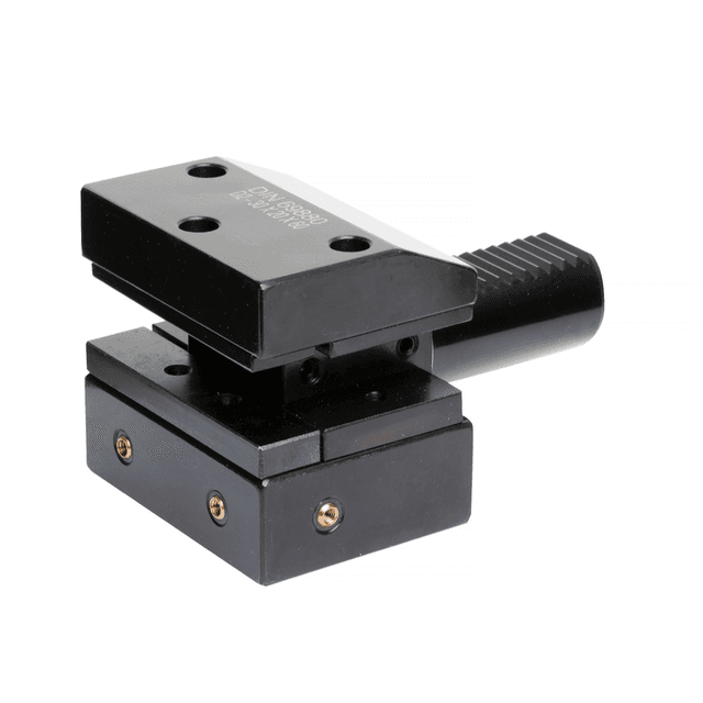
VDI D2 Square Seat Holder
Series: VDI-D2
VDI D2 square seat holder. Upside down multiple square seat holder. Manufactured to DIN69880 standard (ISO 10889).
Starting From:
£213.33 excl. VAT
£256.00 incl. VAT
£213.33 excl. VAT
£256.00 incl. VAT
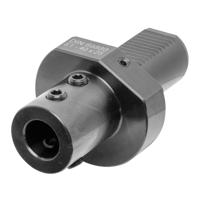
VDI E1 Indexable Drill Holders
Series: VDI-E1
VDI E1 indexable drill holder. Tool holder for holding indexable drills. Manufactured to DIN69880 standard (ISO 10889).
Starting From:
£66.82 excl. VAT
£80.18 incl. VAT
£66.82 excl. VAT
£80.18 incl. VAT
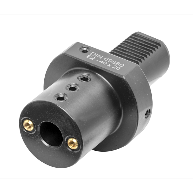
VDI30 E2 Boring Bar Holder
Series: VDI-E2
VDI E2 boring bar holders. Tool Holders for holding Boring Bars. Manufactured to DIN69880 standard (ISO 10889).
Starting From:
£64.42 excl. VAT
£77.30 incl. VAT
£64.42 excl. VAT
£77.30 incl. VAT
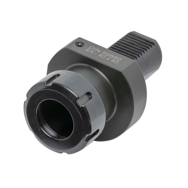
VDI E4 Collet Chucks
Series: VDI-E4
E4 collet chucks. Tool Holders for tools using ER Collet System. Manufactured to DIN69880 standard (ISO 10889).
Starting From:
£92.43 excl. VAT
£110.92 incl. VAT
£92.43 excl. VAT
£110.92 incl. VAT
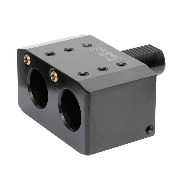
VDI E7 Double Boring Bar Holder, Right
Series: VDI-E7
VDI20 E7 Double Boring Bar Holder. Double Boring Bar Holder for clamping right handed boring bars. Manufactured to DIN69880 standard (ISO 10889).
Starting From:
£229.33 excl. VAT
£275.20 incl. VAT
£229.33 excl. VAT
£275.20 incl. VAT
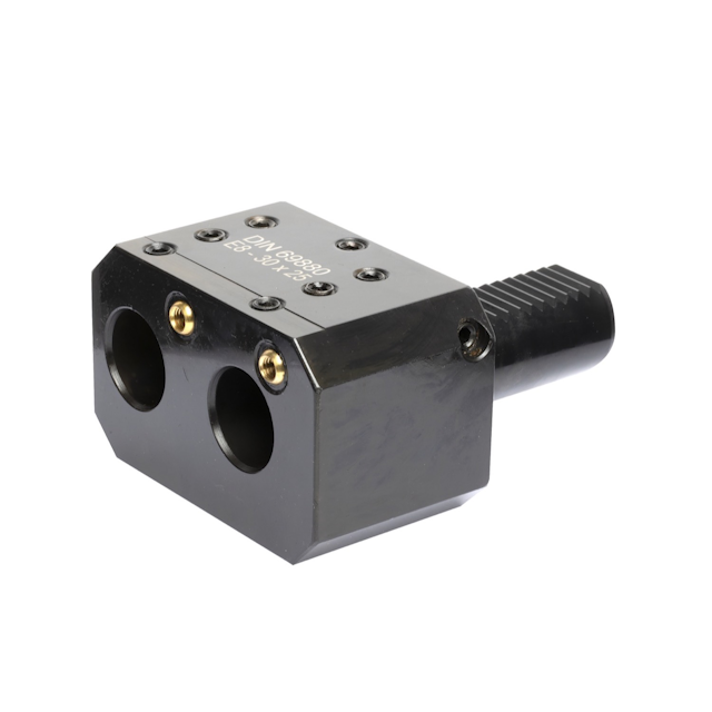
VDI E8 Double Boring Bar Holder, Left
Series: VDI-E8
VDI20 E8 Double Boring Bar Holder. Double Boring Bar Holder for clamping left handed boring bars. Manufactured to DIN69880 standard (ISO 10889).
Starting From:
£232.00 excl. VAT
£278.40 incl. VAT
£232.00 excl. VAT
£278.40 incl. VAT
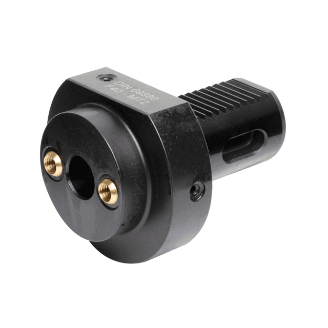
VDI F1 Morse Taper Shank Adaptor
Series: VDI-F1
F1 Morse Taper Shank Adaptor. For Mounting Tools with Morse Taper Shank. Manufactured to DIN69880 standard (ISO 10889).
Starting From:
£94.67 excl. VAT
£113.60 incl. VAT
£94.67 excl. VAT
£113.60 incl. VAT
Frequently Asked Questions
A VDI static tool holder mounts a stationary cutting tool (a turning tool, a boring bar, an indexable drill) in the turret of a CNC turning centre that carries the VDI disc interface. The VDI shank of the holder drops into a matching bore on the turret disc and clamps by a radial serrated coupling, with an axial drive key transmitting rotation to driven holders (or standing idle for static holders). VDI is the DIN 69880 / ISO 10889 standard, so VDI holders fit any lathe with a VDI turret regardless of make.
These holders are used on the generation of CNC lathes fitted with VDI disc turrets such as older Mazak, Doosan, Mori Seiki, Hardinge, Gildemeister/Graziano, HAAS and many others.
A VDI 30 holder fits a VDI 30 turret, a VDI 40 a VDI 40 turret, and so on; the selection is by the VDI shank size, then by the holder type and orientation the work needs.
The number is the nominal diameter of the VDI shank, in millimetres.
A VDI 30 holder has a 30 mm shank, a VDI 40 a 40 mm shank and so on up through VDI 50 and VDI 60. The size must match the turret (a VDI 40 holder will not fit a VDI 30 turret or vice versa) and the size scales with the lathe: VDI 30 suits compact lathes, VDI 40 the mid-frame turning centres (the most common), VDI 50 and VDI 60 the larger lathes with the bigger turrets.
On a modern lathe the VDI size is stated in the machine manual and on the turret itself; if you are unsure, measure the diameter of the VDI shank bore on the turret or count the tool stations — a VDI 30 turret typically carries 10–12 stations, a VDI 40 12, a VDI 50/60 12 in a larger body.
Getting the VDI size right is the first selection, because everything else (the holder length, the centre height and the clamping) derives from it.
DIN 69880 is the German standard (adopted internationally as ISO 10889) that defines the VDI turret interface: the shank dimensions, the serrated radial coupling, the drive-key orientation and the clamping method. Because it is a written standard, a holder made to DIN 69880 fits any turret made to the same standard, which is why VDI tooling is interchangeable across makes in a way the proprietary bolt-on interfaces of newer lathes are not.
In practice the standardisation means you buy VDI tooling by the interface size and the holder designation, not by the machine make. A VDI 40 boring bar holder listed here fits a VDI 40 turret on a Mazak, a Doosan, a Mori Seiki or any other make to the standard.
The corollary is to choose the correct VDI size because the standard guarantees the fit, but only if the size is right.
The letter designates the holder type within the VDI standard.
The A series are pre-machined blanks (A1 a rectangular blank, A2 a circular blank) that you machine yourself to build a one-off holder. The B series are the radial square-shank holders; B1 right-hand short, B2 left-hand short, B3 and B4 the overhead right- and left-hand short, B5 and B6 the right- and left-hand long, B7 and B8 the overhead long. The D series are boring-bar and indexable-drill holders, the E series the ER collet chucks and the Morse-taper holders carry the MT designations.
The numbering within each letter encodes hand and length; odd numbers tend to the right-hand and even to the left-hand, "short" and "long" describe the reach from the turret face. So a VDI-B5 is a radial, right-hand, long square-shank holder; a VDI-D1 is a boring-bar holder; a VDI-E1 is an ER collet chuck.
Knowing the letter tells you the holder type and the number narrows it to the exact orientation and length.
For OD turning and facing with a square-shank indexable turning tool, choose a square-shank holder from the B series; the radial square-shank holders, B1 through to B8. The right-hand holders approach the work from the front-right of the turret and are the standard choice for a turning tool; the left-hand holders approach from the front-left and are used where the part geometry or the turret rotation puts the cut on that side.
Within the right-hand options, the short holders (B1, B3) suit compact turning close to the turret face and the long holders (B5, B7) reach further out (useful for clearing a steady, a tailstock or a larger chuck, or for reaching past a shoulder).
The overhead variants (B3, B4, B7, B8) invert the tool to work from the top of the part, which is how a turret station reaches a cut that a normal-orientation tool cannot.
A starter kit usually has a pair of short right-hand holders; one for the rougher, one for the finisher.
The hand of a VDI holder describes the orientation of the tool seat relative to the turret (a right-hand holder seats the tool to cut as the turret rotates one way, a left-hand holder the other). In practice a right-hand holder is used for cutting toward the headstock (the conventional turning direction) and a left-hand holder when the cut runs the other way (back-facing a shoulder, machining a back-face, or reaching the second side of a sub-spindle part).
On a twin-turret or twin-spindle machine the left-hand holders come into their own, because the second turret or sub-spindle often needs to approach the cut from the opposite side. Single-spindle lathes without a sub-spindle mostly use right-hand holders.
The incorrectly-handed holder turns the wrong way and cannot reach the cut, so if the part has features on both faces the kit will need both hands (it is worth checking the process before ordering only the right-hand set).
An overhead holder (the B3, B4, B7 and B8 in the VDI range, flagged in the filters as "Overhead (Upside Down)") mounts the tool inverted, with the cutting edge uppermost rather than in the normal lower position.
That inverts the approach of the tool, so the turret reaches cuts that a normal-orientation holder cannot reach; typically back-facing operations, under-shoulder work and cuts where a normal tool would foul the chuck or the workpiece.
Overhead tooling earns a place on lathes doing a lot of back-working or in twin-turret configurations where the opposing turret must approach the part from above.
A standard single-turret lathe rarely needs overhead holders, but a lathe with a sub-spindle or a steady often does; the overhead tool can back-face and back-turn the second side of a part while the main turret handles the front.
If you are buying tooling for a sub-spindle or twin-turret machine, plan for some overhead stations.
Internal turning of a bore is done with a boring bar held in a VDI boring-bar holder (the D series). The holder takes a cylindrical boring bar on a set centre height and clamps it firmly to resist the chatter that internal work invites; the bar is chosen separately for the bore diameter and depth and the holder for the bar shank size and the VDI turret size.
For a deeper or more rigid bore, an indexable drill holder carries an indexable drill (a drill that inserts a replaceable carbide tip, used for larger-diameter deep holes) at the right centre height and with the through-coolant supply those tools need. The boring-bar holder is the everyday internal-turning choice; the indexable drill holder is for the heavier, larger-diameter starting-hole work where an indexable drill outperforms a solid drills.
A VDI ER collet chuck (the E series) is a static VDI holder with an ER collet pocket in the working end, clamped by a collet nut. On a static turret it is used to hold a cylindrical tool shank (typically a solid drill, a reamer, a spot drill, a small boring head) on the centre line, carried in the turret instead of in the tailstock. That brings the drilling and reaming onto the turret, where the indexing takes the tool to centre line repeatably and the CNC controls the depth.
It is the bridge between "static" tooling and rotary cutting on the turret: the collet chuck does not drive the tool (it is a static holder, the tool rotates by being driven through the spindle or by the workpiece), so it suits tools that cut as the spindle turns the work (drill, reamer and similar).
For a tool that must rotate while the workpiece is stationary (milling) you need a driven holder, not a static collet chuck.
A VDI Morse taper holder carries a Morse-taper-shanked tool (typically a drill, a reamer, or a small boring head) by seating the taper in a matching MT socket in the working end of the VDI holder.
The Morse taper is the classic self-locking method for mounting a tool on a taper, transferring the drive by friction; the holder brings a standard MT-shanked tool into the turret where it can be indexed and positioned by the CNC.
It suits tools supplied on a Morse taper (many larger drills and reamers and some boring heads) and is a useful holder where you already have a library of MT-shanked tooling.
For new tooling an ER collet chuck is generally more flexible but the Morse taper holder earns its place where the tooling is already on MT or where the rigidity of a taper seat is wanted for a heavier drill.
The A1 and A2 are pre-machined VDI blanks (A1 a rectangular block on a VDI shank, A2 a circular block on a VDI shank) supplied with the VDI interface finished but the working end left as a solid block for you to machine to a custom shape. They let you build a one-off holder for a non-standard tool, a special boring-bar size, a profiled form tool or any tool that the standard VDI holder range does not cover.
They suit shops doing specials, form tools and prototype tooling where an off-the-shelf holder is not available, you machine the pocket, seat or bore to suit the tool, on a mill and the VDI interface is already finished to standard so it mounts on the turret correctly.
The blanks are bought at the VDI size of the turret; the A1 rectangular blank gives a square working face for square-shank and form tools, the A2 circular blank suits cylindrical seats and boring bars.
Many VDI static holders are available with through-tool coolant (the coolant is fed through the holder and the tool, rather than only externally) and that makes a real difference for the internal work where external coolant struggles. A boring bar with through-coolant delivers fluid to the cutting edge at the bottom of the bore, flushing chips and cooling the edge directly; an indexable drill holder with through-coolant is essential because indexable drills are designed to run with coolant through.
Through-coolant is specified by choosing the through-coolant variant of the holder and matching it to a coolant-through tool and routing the machine’s turret coolant supply to the holder (most VDI turrets carry coolant to the stations).
If your machine has through-coolant at the turret, it is the right choice for boring and drilling; if the turret only has external coolant, the through-coolant holder is still usable but you forgo the benefit.
Check the turret spec before ordering, because the through-coolant holder is slightly more expensive and only earns its keep when the supply is wired.
Centre height (the distance from the spindle centre line to the cutting tip) must be exact for an accurate diameter and a clean finish. A VDI static holder is designed to set the tool close to centre through its dimensions, with the final adjustment by shims beneath a square-shank tool, by the height adjustment on a boring-bar holder or by the nut and collet on a collet chuck. Set the tip to centre with a height gauge or by touching a bar held between centres, then lock the tool.
A tool above or below centre, even by a few hundredths, turns a tapered part and produces a poor finish, because the tool geometry is designed to cut at centre. The effect is most visible on diameters since a Part turned with the tool off-centre will not gauge, and the taper will chase you around the part.
Take the time to set centre once per holder; the VDI system repeats that setting when the holder indexes, so the work is not repeated every cycle.
Keep the VDI shank and coupling clean. The accuracy of a VDI system depends on the holder seating cleanly in the turret bore and the serrated radial coupling engaging correctly because swarf and coolant residue between the mating faces is the most common cause of a holder not indexing true, which shows up as a poor or tapered part. Wipe the VDI shank and the coupling before fitting, and confirm the clamping bolt or radial clamp is torqued to spec because a loose holder shifts under cut.
The drive key on a static holder is usually a blank key or a "false" key (the holder does not drive), and it should be present and correctly oriented because a missing or wrongly-fitted key lets the holder seat off-position.
On the working end, keep the collet and nut of a collet chuck clean and inspect a boring-bar holder’s clamping screw and seat for wear.
Store spare holders clean, racked, with the tooling left in place where possible (a pre-set holder returns to the turret ready to run).
Begin with the plain-turning set: a pair of right-hand short square-shank holders (B1) for your main roughing and finishing turning tools, a boring-bar holder (D series) for the internal work and a collet chuck (E series) for the centre-line drilling and reaming.
That four-holder set covers the bulk of turning, boring and drilled-feature work and lets each tool have its own permanent turret station.
Add a parting block if the parting operation is in the main turret.
From there add as the work demands; a left-hand holder for back-facing, an overhead holder for a sub-spindle or steady, a Morse-taper holder for existing MT-shanked drills and additional square-shank holders so the rougher, finisher, profiling tool and threading tool each have a home.
Tell us your lathe, the VDI size and the parts you intend to make and our engineers will put together a matched VDI holder list that fits the turret and covers the work from the first set-up.